Tooling is the backbone of plastic injection molding. Without a proper tool design, your plastic part would never scale up properly. A quality tool design can save you enormous amounts of time and money during production. Before contacting a product development company to design your tools, here are a few facts about tooling you should keep in mind.
What is tooling?
Tooling, also known as a mold, refers to the negative cavity space where molten plastic resin is injected to create a part. High quantity and quality parts require proper tooling. Since tool design and construction are complex, fabrication requires significant capital investment and enough lead time to create an effective tool.
Prototype tooling and prototype tools
The tooling design process starts out in the prototype development phase. Here 3D printing, cast urethane, and machining techniques create prototype tools. These low-volume prototypes troubleshoot, develop, and validate the tooling design during new product introduction. While this step may seem unnecessary, cutting down on errors in the manufacturing and assembly process early can significantly decrease time and cost later. Learn other ways to control costs in our “How Much Does Product Development Cost” FAQ.
Considerations when designing a tool
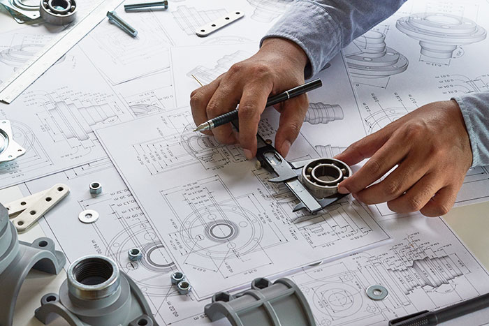
Proper tooling design and choices need to accommodate for complexity, lifetime, application, and potential production volume of the tool. Choosing which tooling method to invest in is the hardest part of the tooling process. If the part is going straight into high volume contract manufacturing, then it will be most cost-beneficial to invest directly into expensive production tooling for the long term. In other cases, such as low volume manufacturing, using a prototype tool may be more beneficial until production increases significantly.
Toolmakers provide necessary assistance with the tool design process because they are well-versed in fabricating techniques and tooling design. They can run mold flow analyses to optimize the tooling design and choose the best locations for parting lines, gate, and ejection locations. A quality prototype design engineer will work closely with toolmakers to ensure the fabrication of the optimal tool for your application.
How to design and make a tool
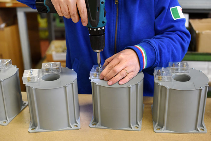
After collaborating with the toolmakers on the design, the part is ready and approved for the T1 sampling stage. They will build the first tool with a 2-16-week lead time dependent on design considerations. T1 sampling demonstrates that the tooling functions correctly and produces ideal parts. After the T1 sampling is accepted, any necessary modifications and aesthetic mold texturing can begin. These additional modifications can take 1-2 weeks to complete. The modified molds, referred to as T2 samples, are sent for approval of texture and appearance. Once the T2 samples are approved, the toolmaker releases them to the contract manufacturer.
Once with the manufacturer, the T2 samples are placed into the production line for process development and part qualification. The tooling undergoes a series of molding studies that help outline the optimal conditions and characteristics for creating parts using that tool. The manufacturer runs experiment trials to isolate process inputs and corresponding impacts on part characteristics. This initial testing helps the molder validate an ideal processing window that produces parts within specification.
After initial process development, qualifications, and validations, the tool enters a regular production maintenance schedule. Here the tool is regularly monitored for wear and other potential issues affecting part quality or tooling lifetime.
Basic features of a tool
- Cavity half – The cavity half is the side of a tool that does not move. It is typically attached to the side of the molding machine.
- Core half – The side of the tool that opens and closes with the mold machine against the cavity half. It opens when removing the part from the tool.
- Cooling lines – Channels that allow coolant to flow throughout the tool and control the cooling of the plastic part.
- Ejector system – Pins on the core half of the tool that helps push the cooled part out after molding.
- Runner – A flow path for the plastic resin allowing the press to inject material directly into the part cavity.
- Side actions – Moving pieces within the part cavity added to allow for undercuts.
The entire process from prototype to production can take months and significant investment to properly complete. Therefore it is vital to design your parts for manufacturing throughout product development. A product design prototyped using machining, or 3d printing, may not easily translate to a tooling design for high volume production. We recommend partnering with a product development company intimately familiar with the tooling design and the manufacturing process that will provide you with the best tooling deliverables possible. You can learn more about deliverables in our “What are the Key Deliverables in the Product Development Process” FAQ.
Need Tooling?
About Synectic Product Development: Synectic Product Development is an ISO 13485 certified, full-scale product development company. Vertically integrated within the Mack Group, our capabilities allow us to take your design from concept to production. With over 40 years of experience in design, development, and manufacturing, we strive for ingenuity, cost-effectiveness, and aesthetics in our designs. Learn more about our contract manufacturing services and see how we can help your next project.