Snap fit joints are a simple, reliable, and cost-effective method for assembling plastic parts without needing additional fasteners or adhesives. Among various types, cantilever snap joints are one of the most commonly used due to their ease of design and effectiveness. However, you should follow established snap fit design principles to ensure proper function and avoid part failure. This article outlines the key factors that influence cantilever snap joint performance and provides a real-world design example to demonstrate how these principles are applied.
Key Factors in Cantilever Snap Joint Design
The most basic snap fit design is a rectangular cantilever beam with a uniform cross-section. To design a robust part, you must carefully consider the geometry of the cantilever beam and the mechanical properties of the material. Ignoring these principles can lead to overstressing, part failure, or excessive insertion forces that compromise assembly. The performance of a cantilever snap-fit depends primarily on the following design parameters:
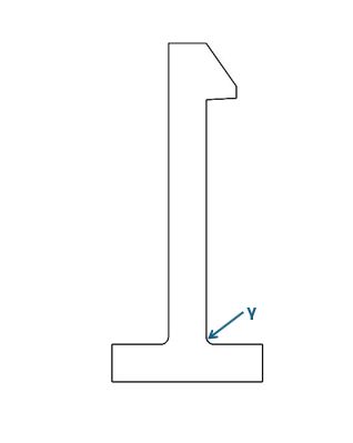
Maximum snap deflection (Y)
Maximum snap deflection is the displacement of the beam tip required to engage or disengage the joint with the mating part without failure. It must remain below the maximum permissible strain of the plastic material to avoid permanent deformation or fracture. Essentially, it tells you how far in inches the arm can bend before stressing the material too much. You can calculate the maximum allowable deflection by:
Y = 0.67 ∗ ( (Ɛ ∗ L²)/ H)
Where:
L = Snap Beam Length – The length of the beam arm.
H = Snap Beam Thickness – The thickness of the beam arm at the root.
Ɛ = Maximum Permissible Strain – Permissible strain is a material property, and it can be estimated from the material’s flexural strength and modulus of elasticity. You can also find it listed in the material’s datasheet. For polycarbonate (PC), typical values range between 4% and 8%.

Snap deflection force (P)
Snap deflection force is the peak force required to elastically deflect the snap arm to its maximum deflection (Y). You can think of it as the theoretical bending force. It is calculated using:
P = (B ∗ H² ∗ E ∗ Ɛ)/ 6L
Where:
H = Cross Section Width – The width of the beam arm at the root.
B = Snap Beam Thickness – The thickness of the beam arm at the root.
E= Modulus of Elasticity – How stiff the snap arm is. This information is listed in the material’s data sheets. For example, if your material is polycarbonate, the modulus of elasticity would be ~2,400 MPa (350,000 psi).
Ɛ = Maximum Permissible Strain – described in the previous section.
L = Snap Beam Length – The length of the beam arm.

Snap frictional force (F)
Snap frictional force is the force required to pull the snap apart. It tells you the snap fit’s resistance to coming apart after assembly. The formula for calculating the frictional force is:
F = (µ + tan γ)/ (1 – µ tan γ)
Where:
E = Modulus of Elasticity – described in the previous section.
γ = Entry Angle – The entry angle is the angle of the inclined surface of the snap feature that guides the mating part during assembly. A steeper angle reduces the displacement required for engagement but increases the insertion force. To balance manufacturability and usability, we recommend an entry angle of less than 45°.
µ = Coefficient of Friction – This is between the snap and the mating wall. This value can be found in the material’s data sheet and is usually 0.2 -0.4 for plastic.
Snap assembly force (W)
Snap assembly force, also referred to as the mating force, is a combination of the deflection force and frictional resistance. It is the actual force you must apply during assembly to push the two parts together so that the snap fully engages. It is greater than the deflection force (P) because friction (F) is also a factor. Using the values you’ve calculated previously, you can determine the snap assembly force with the following formula:
W = P ∗ F
Where:
P = Snap Deflection Force
F = Snap Frictional Force
At the end of this section, you should be able to determine:
- How far it bends (Y)
- How much force you need to bend it (P)
- How much it holds after snapping in (F)
- How much force is needed to assemble (W)
Additional design guidelines
Tapered beams
Using a tapered cantilever beam (thicker at the base) will provide a more evenly distributed stress along the beam to avoid concentration points that could lead to failure, as well as increase the snap deflection if desired. The rule of thumb is to reduce the thickness at the end of the beam to one-half the value at the root. In this case, you can calculate the snap deflection similarly by replacing the 0.67 value with 1.09 in the formula above.
Fillets at the root
Generous fillets at the bottom of the beam are required to reduce stress concentration. Care should be taken to avoid overly thick sections that can cause sink and/or void in molded parts. However, we recommend radii no less than 0.4 mm.
Avoiding sink and voids
Very thick sections near the root can cause molding defects such as sink marks or voids. Maintaining balanced wall thicknesses helps preserve both aesthetics and strength.
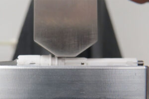
Example: injection molded spring finger
An application of these cantilever snap design principles was used for the following example of an injection molded spring finger. In this case, the cantilever beam is intended to supply a retention force to a part that is free to rotate relative to the base part.

The snap beam has the following dimensions:
- Length, L = 8 mm
- Width, H=1.5mm
- Thickness, B=3mm
- Material: Polycarbonate (PC) with flexural modulus E=2350MPa and maximum permissible strain Ɛ=4%
Step 1: maximum allowable deflection
Y = 0.67 ∗ ( (0.04 ∗ 8²)/ 1.5) = 1.14mm
Applying a 10% safety factor: Y=1.0mm
Step 2: snap deflection force
P = (3 1.5² ∗ 2350 ∗ 0.03)/ (6 ∗ 8) = 13 N
Step 3: snap frictional force
F = (0.3 + tan 60)/ (1 – 0.3 tan 60) = 4.2 N
Step 4: snap assembly force
W = 13 ∗ 4.2 = 54 N
This retention force is confirmed as acceptable for the original design intent, and the part design can be finalized for production.
By understanding and applying the fundamentals of cantilever snap-fit design, you can create durable, manufacturable plastic assemblies that perform reliably under repeated use. If you need help designing snap-fit features into your product, Synectic’s product design services include DFM-aware mechanical design from concept through CAD.
Properly calculating snap deflection and assembly force ensures functionality and helps prevent common issues such as overstressing, breakage, or excessive insertion force. As demonstrated in the spring finger example, straightforward calculations and design best practices allow for effective validation before prototype development and production. With attention to material properties, geometry, and stress distribution, snap-fit joints can be a powerful tool in any product designer’s toolbox.
Already have a snap-fit design?
About Synectic Product Development: Synectic Product Development is an ISO 13485 certified, full-scale product development company. Vertically integrated within the Mack Group, our capabilities allow us to take your design from concept to production. With over 40 years of experience in design, development, and manufacturing, we strive for ingenuity, cost-effectiveness, and aesthetics in our designs.