Ultrasonic welding is one of the most efficient ways to join plastic components in manufacturing, but getting it right depends heavily on the joint design, especially the energy director. This small but critical feature plays a big role in directing heat where it is needed for a clean, strong weld. Whether you are new to ultrasonic welding or looking to improve weld consistency, understanding the role of energy directors and how they change based on joint type is key. In this article, we break down the most common ultrasonic weld joints and the design rules that go along with them in an end to end product development process
What is ultrasonic welding?
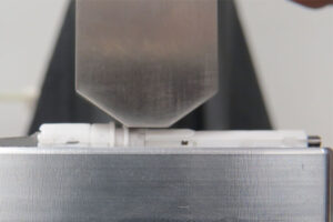
Ultrasonic welding is a process that uses friction to heat plastics to a high temperature and bond them together. Ultrasonic vibration allows high energy levels to be transferred to a plastic part without causing stress, cracks, or residual deflection in the welded material. This makes ultrasonic welding a desirable way of joining separate parts in manufacturing. If you already have a design that uses ultrasonic welding, a DFM review can validate your energy directory geometry and joint design before tooling is committed, see more about our DFM services.
What are the types of ultrasonic energy directors?
A basic design requirement of any joint that utilizes ultrasonic welding is to incorporate an energy director. An energy director is a small, uniform initial contact area with a triangular cross-section designed into the molded parts geometry. The energy director’s design requirements depend on the type of joint used, with the most common being the Butt Joint, Step Joint, Tongue and Groove Joint, and Shear Joint.
Butt joint
The butt joint is the most common joint used in ultrasonic welding. Modified with the triangular energy director, the initial contact is limited to a very small area, focusing ultrasonic energy at that point. The height and width calculations of the energy director are determined by the angle of the triangular joint, either 90° or 60°. Practical considerations require a minimum energy director height of .010”/.25mm to ensure a consistent weld to the material.
- 60° Butt Joint: Energy director height should be 1/4.5 of the joint width, and the width should be ¼ of the joint width.
- 90° Butt Joint: Energy director height should be at least 1/10 of the joint width, and the width of the energy director should be at least 1/5 of the joint width.
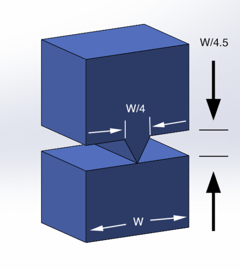
60 degree butt joint
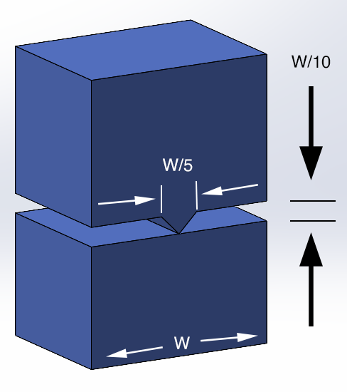
90 degree butt joint
Step joint
The step joint is commonly used when the cosmetic appearance of the part is important, as it provides a good alignment and a flash-free joint. The energy director height and width are calculated similarly to a 90° butt joint, with additional limitations to the step height and width, as seen below.
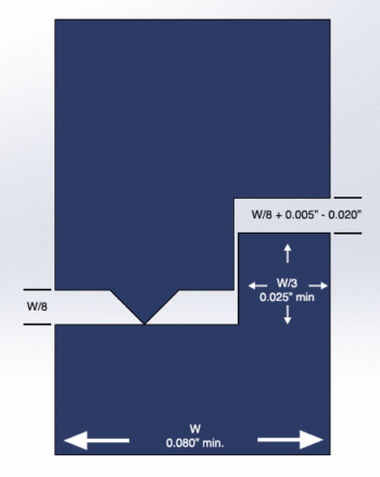
Step Joint
Tongue and groove joint
Tongue and groove joints are primarily used for scan welding, self-location of parts, and prevention of internal and external flash. The joint is not used as often as other methods, as it requires maintaining equal clearance on both sides of the tongue, which is difficult to achieve in the mold. Design limitations for the energy director are similar to the butt joint, with the tongue and groove requirements listed below.
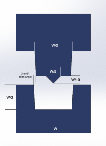
Tongue and Groove Joint
Shear joint
Used when a strong hermetic seal is needed for crystalline-based resins. A shear joint is accomplished by first melting the small initial contact area and then continuing the melting process with controlled interference along the vertical walls as the parts telescope together. A small lead-in is necessary for self-locating the parts into the shear joint. This process requires longer weld times due to the amount of resin that needs to melt and bond together, with the two parts ‘smearing’ into one another. The joint requirements are listed below.
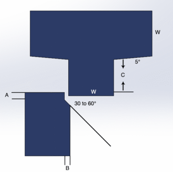
Shear Joint
Other joint types
Some other types of joints utilized consist of variations in the direction of the energy director(s), providing a larger surface area and/or a stronger bond. However, these might produce additional flash or be costly to mold into the part geometry. These consist of the following:
- Criss-Cross joint
- Textured surface joint,
- Perpendicular energy directors
- Interrupted energy directors.
Criss Cross Joint
Other ultrasonic welding methods
Staking
Staking is an assembly method that uses the controlled melting and forming of a plastic stud or boss to secure or lock another material, such as a PCB or metal component, in place.
Stud welding
Stud welding is an alternative to staking that joins plastic parts as single or multiple localized attachment points. Stud welding is useful when a continuous weld is not required.
Spot welding
Spot Welding is a technique for joining two thermoplastic components at localized points with no preformed hole or energy director. Spot welding produces a strong structural weld and is well-suited for large parts.
How to calculate the energy required for ultrasonic welding
When selecting to use an ultrasonic weld in manufacturing, it is necessary to ensure how much energy is required to create the weld. We can calculate the energy required using the following formula:
E=PxT
Where:
E=energy
T=time
P=power,
Power= force (F) x velocity (V)
Force derives from the down speed and pressure of the horn, and velocity derives from frequency and amplitude.
The parameter with the most influence within ultrasonic welding is the amplitude, which is the peak-to-peak longitudinal displacement experienced at the face of the horn. The heat generated at the joint is based on amplitude squared, thus having a greater effect on the outcome of the joint. The amplitude is determined by the selected frequency and the material or resin you choose for your parts.
Often, you can find amplitude reference guides that provide guidelines for amplitude settings based on the parameters of your machine and the material or resin. Overall, the greater the amplitude, the greater the welding energy you will have.
While there is no single equation to calculate the predicted strength of an ultrasonic weld based on the machine settings selected and the molded parts geometry, the parameters mentioned above significantly influence the weld strength. You can use these parameters to estimate the relative strength of the weld. Additional parameters such as weld time (the duration of time you apply ultrasonic vibration to the parts), and the hold time (the duration you need to maintain pressure to ensure parts bond and the weld cools) are also important to the outcome of a strong joining of the parts.
At the end of the day, successful ultrasonic welding starts with smart energy director design. From choosing the right joint geometry to calculating energy director dimensions and understanding how amplitude and weld time affect the outcome, every detail matters. Getting those details right early in the design process can save time, reduce rework, and lead to more reliable welds on the production floor. If you’re unsure about your energy director design or how to optimize it for your application, working with your ultrasonic equipment provider, or an experienced product development company, can make all the difference.
At the end of the day, successful ultrasonic welding starts with smart energy director design. From choosing the right joint geometry to calculating energy director dimensions and understanding how amplitude and weld time affect the outcome, every detail matters. Getting those details right early in the design process can save time, reduce rework, and lead to more reliable welds on the production floor. If you’re unsure about your energy director design or how to optimize it for your application, working with your ultrasonic equipment provider, or an experienced product development company, can make all the difference.
Need ultrasonic welding designed into your assembly from the start?
About Synectic Product Development: Synectic Product Development is an ISO 13485 certified, full-scale product development and design. Vertically integrated within the Mack Group, our capabilities allow us to take your design from concept to production. With over 40 years of experience in design, development, and manufacturing, we strive for ingenuity, cost-effectiveness, and aesthetics in our designs.