3D printing is a prototyping method that “prints” a three-dimensional physical object in layers from a digital file. Compared to traditional prototyping methods, 3D printing is fast and low-cost. While 3D printing appears to be the magic solution for all design challenges, there are limitations to the technology. Therefore, one must consider these limitations and incorporate, eliminate, or adjust certain features to optimize the prototype design for 3D printing. This article covers the most common considerations and how to incorporate them when designing for 3D printing.
Available 3D Printing Technology
There are multiple technologies available for 3D printing, with new technologies becoming available regularly. In this article, we will discuss the following five most used technologies:
Carbon
Great for prototypes & end-use production parts.
FDM
A low–cost option for prototypes, production parts, jigs, and fixtures.
MJF
A fast option to print batch production parts.
SLA
Great for low-cost design models, fit & function models, master patterns, & show models.
SLS
An option for creating strong prototyping and production pieces.
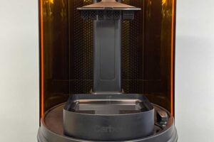
Carbon DLS (Digital Light Synthesis)
Carbon DLS uses CLIP (Continuous Liquid Interface Production) technology, where the machine projects light through an oxygen-permeable window into a reservoir of UV-curable resin. The platform raises continuously as the resin flows past the light, building the part upside-down. After printing, the part is baked and undergoes a secondary chemical reaction to finish the curing process and add strength. Carbon DLS is best for end-use parts or parts that require biocompatibility. For more information about available materials for Carbon DLS, see our spec sheet.
Pros
• Produces isotropic parts having complex geometries.
• Parts can be flexible with a smooth surface finish, making them suitable as end-use parts.
• Product-grade materials, including food-grade and biocompatible materials.
Cons
• Carbon DLS is one of the most expensive 3D printing technologies.
• Not suitable for bulky, thick, or large parts.
FDM (Fused Deposition Modeling)
FDM uses layers of molten thermoplastic filaments extruded through a nozzle onto a platen. After completing each layer, the nozzle moves upwards, building the part layer by layer. FDM is best for jigs, fixtures, and small to large prototypes.
Pros
• Low-cost and easily accessible for even amateur engineers.
• Material can be the same as those used for injection molding (ABS, PC), producing parts suitable for testing end-use materials.
• Machines are relatively inexpensive, with many available options.
Cons
• The resolution is not as good as some other 3d printing technologies.
• Parts are not watertight.
• Requires support material, adding extra cost and time.
MJF (HP's Multi Jet Fusion)
MJF uses proprietary technology to build parts by fusing powdered nylon on a heated printing bed. First, the inkjet nozzles spray detailing and fusing agents on the powder, creating the part geometry. Then a heat lamp sets the powder into a layer. After completing each layer, the printing bed moves down to make room for the next layer. MJF is best for small to medium prototypes and end-use production parts. For more information about available materials for MJF, see our spec sheet.
Pros
• MJF produces highly accurate complex parts fast.
• Parts are robust, with isotropic mechanical properties.
• Builds do not require support material.
Cons
• Limited available material options.
• MJF cannot produce curved or hollow parts.
• Parts are rough with a black or gray finish.
SLA (Stereolithography)
SLA is the oldest 3D printing technology on the market. It operates by focusing a UV laser into a vat of photopolymer resin to cure the resin in layers. Similar to FDM, SLA machines use a platen to support the build. Unlike FDM, the platen, not the nozzle, moves down as the part builds upside down. SLA is best for small to large prototypes and master patterns. For more information about available materials for SLA, see our spec sheet.
Pros
• SLA produces parts with excellent resolution. Part surfaces are smooth without visible steps.
• Parts can be small and detailed with a high degree of accuracy.
• Depending on the resin, the parts can be watertight and/or translucent.
Cons
• Parts are photosensitive, leading them to degrade and become brittle over time.
• Parts are affected by moisture, chemicals, and heat.
• Requires support material, adding extra cost and time.
SLS (Selective Laser Sintering)
SLS is a type of powder bed fusion technology similar to MJF. It uses a laser to sinter (fuse) thermoplastic polymer powder layer by layer. Unlike MJF, where fusion happens in a line, SLS fuses each section point-by-point. SLS is best for small to medium prototypes and end-use production parts.
Pros
• SLS Produces parts requiring complex geometries with few design constraints compared with other technologies.
• There are a large variety of materials available.
• Parts are functional and high-quality without needing support.
Cons
• The powder is only 50% recyclable, making it best suited for batch production due to cost.
• Cooling time is 50% of the total print time, slowing production.
• Parts can warp or shrink depending on the direction they are built.
Minimum Feature Size
DLS
0.009" - 0.019"
FDM
0.078"
MJF
0.019"
SLA
0.03"
SLS
0.03"
Different 3D printing processes have different size limitations associated with minimum feature size (resolution). Part designers should consider feature size limitations when designing small features. If the printer cannot accommodate the small size, it may misprint or eliminate those features regardless of whether they are on the CAD model.
Carbon DLS – The minimum feature size is material-dependent but is typically between 0.009″ and 0.019″.
FDM – Nozzle diameter determines minimum feature size. The standard minimum is 0.078″ but the geometry and material can require a larger minimum size to maintain feature integrity.
MJF – This technology can produce exceptionally small, detailed parts with a minimum feature size of 0.019″ and layer thickness of 0.003″.
SLA – The minimum feature size for SLA is 0.03″. Part orientation is also a factor because the smallest feature size in the XY orientation cannot be smaller than the laser spot size.
SLS – SLS is similar to SLA with a minimum feature size of 0.03″.
Holes
Because 3D printing builds in layers, as the materials cure, the layers can compress, causing holes to be smaller than expected. To compensate for over-cure horizontal holes should be oversized. The amount of oversizing depends on the material and 3d printing technology. You may need to also determine this by trial and error. You can also change the part orientation where the hole is built vertically and is not affected by over-cure or layer compression.
Carbon DLS – Horizontal holes should be oversized by at least 0.001″ to compensate for over-cure. Hole diameter minimums are between 0.019 and 0.078″, depending on the material and hole orientation.
FDM – FDM has one of the largest hole diameter requirements at 0.078″.
MJF – Minimum hole diameter for MJF is 0.019″.
SLA – Holes with a diameter less than 0.031″ in any axis could close off during printing.
SLS – To maintain integrity, holes require a diameter greater than 0.059″.
Overhangs and Supports
3D printing builds material on top of material in layers. If there is no support material underneath each layer and the material is not connected to another point, it is considered an overhang. If you use a technology requiring support material, it is best to reduce the number of overhangs as supports produce a rougher surface finish. You can reduce the number of overhangs by changing the build orientation. Orient your parts to maximize build efficiency and reduce overhangs, bridges, and elements that reduce print quality. Most often this means changing an element from being printed on the Z axis to the XY axis. You can decrease cost and build time by reducing support requirements as much as possible.
Carbon DLS – The closer a feature is parallel to the platform, the higher the likelihood of failure. The degree limitation depends upon the material but is between 30-40 degrees, while the maximum overhang length is between 0.039″ to 0.011″.
FDM – The overhang limitation is 45 degrees, meaning you cannot print right angles without support.
MJF – Since MJF uses a powder to build the part, this method does not have issues with overhangs as no support materials are required.
SLA – To produce overhangs, an adequate number of supports is required. If there are no supports, overhangs must be limited to 0.039″ and a minimum of 19 degrees. Any geometry over that will cause the overhang to warp or break.
SLS – SLS does not require support material for overhangs because the unsintered powder supports the design while building.
Orientation of the part changes the amount of necessary supports required for the part to successfully print.
Part Orientation
Parts produced via FDM and sometimes SLA, are generally stronger in one direction. Due to how the machine builds the layers, the strongest direction is when the load is parallel to the layers. This also means that the larger the layer’s surface area, the stronger it is. SLS, MJF, and Carbon DLS all produce isotropic parts meaning the strength is the same regardless of the axis. When designing for 3D printing, select the best part orientation to achieve the best strength.
Part orientation can also determine tolerance. 3D printing tends to be micro-precise in length and width but not height. If your part requires a precise height, you should change the part orientation to the XY axis.
How you orient your parts affects build quality and surface finish. For technologies requiring a build plate, whatever surface touches the build plate will be flat or attached via support material.
Build Size
Every 3D prototype machine has a limitation on the maximum size of the build envelope. The taller the build, the more layers are required and the longer it takes to print. If the part is too big, you will need to redesign the part breaking it into smaller pieces and add in interlocking features to fasten or glue them together. If you plan to use glue, you must choose a glueable material. Regardless of the adhesion method, it will add additional steps, materials, cost, and time to part production.
Wall Thickness
Minimum material thickness is a function of the resolution of the machine and the material selected. Typically, rapid prototyping will create a support system for thin walls allowing the wall to be built vertically without warping. Unsupported walls have a greater chance of warping or detaching from the build. When designing for 3D printing you want part walls to be as thin as possible. The aim is to keep costs and build time down while maintaining strength and part integrity.
Carbon DLS – The minimum wall thickness of unsupported walls is 0.09″, while supported walls are 0.04-0.06″, depending on the resin material. Wall thickness should be uniform or have thickness changes as gradual as possible to minimize defects and prevent warping during baking.
FDM – In FDM, nozzle diameter determines wall thickness, and the industry standard is 0.015″. Wall thickness can only be increased or decreased by a factor of the nozzle diameter size. This means that your part cannot have a 0.023″ wall thickness if the nozzle diameter is 0.015″. The rule of thumb in FDM is that the minimum wall thickness size should be 2x the nozzle diameter. Some FDM software will ignore wall sizes that are too thin and not print them, affecting build quality and strength.
MJF – Wall thickness is determined by the wall direction, with 0.011″ for XY orientation and 0.019″ for Z orientation.
SLA – Supported walls should be a minimum of 0.015″ thick. Unsupported walls should be at least 0.02″ thick and have a filleted base where the wall connects to the print. Filleting the base rounds the edge and adds strength.
SLS – Minimum wall thickness depends on the material, but it ranges between 0.027″ and 0.07″. Since SLS does not require support there is no difference in wall thickness for a supported or unsupported wall.
Post-Processing
Post-processing requires additional steps after building that add to the overall part cost and production time. Consider the porosity of the printed part when designing for 3d printing. Some printing technologies produce porous parts that can be sanded, filled, or painted in post-processing. Some solutions offer a denser, more solid part with a better resolution that requires less post-processing.
3d printed parts have layer lines corresponding to the layer thickness. While the XY resolution on industrial 3D printers is exceptional, the vertical offset of material at each elevation will cause steps, resulting in a potential need for additional finishing.
Translucent parts often require a clear lacquer to be sprayed on them. When designing these parts, you should adjust the sizing to account for the added lacquer thickness. This thickness is usually about 0.001 to 0.003″.
Surface Finish
3d printed parts requiring a build plate will generally have an “ugly” side facing the build plate, while the exposed surface has a better finish. The surface difference is because of how the extruded plastic is heated and cooled layer upon layer. Bottom-facing layers cool before getting compressed by the layer above, resulting in a rougher surface. The top layer is nice and compressed, minimizing spaces between the filament, and making the overall surface smoother. Conversely, powder-based technologies will have a grainy finish on their lower surfaces due to the powder on the printing bed.
3D printing is a powerful tool because iteration speed is very fast and can create near-impossible geometries. While one can design parts and make them nearly instantly, ultimately, you should tailor your design for the process that can make the best parts at production volumes. Instead, use the speed of 3D printing to turn prototypes around quickly and iterate faster. In the end, whatever method you choose, the design must balance speed, feature requirements, and cost. Synectic has extensive experience designing parts for 3D printing.
About Synectic Product Development: Synectic Product Development is an ISO 13485 certified, full-scale product development company. Vertically integrated within the Mack Group, our capabilities allow us to take your design from concept to production. With over 40 years of experience in design, development, and manufacturing, we strive for ingenuity, cost-effectiveness, and aesthetics in our designs. Learn more about our prototype development services and see how we can help your next project.